PART CONSTRUCTION & MANUFACTURING ISSUES
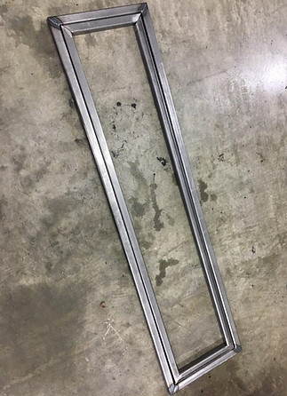
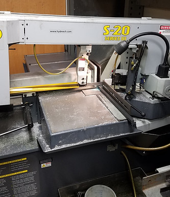
The construction process began by first manufacturing the upper and lower frames, this is was the starting point of the Auto-jack. The overall length tolerance of 0.125" was crucial when taking the initial cuts, if the upper frame wasn't cut to spec the upper frame wouldn't retract inside the lower frame and Auto-jack wouldn't meet the set design requirements.
Manufacturing issues:
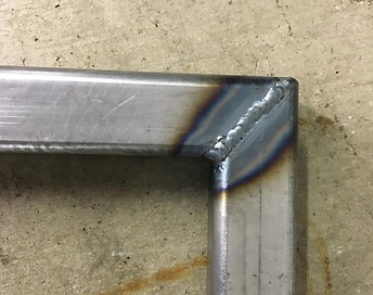
The issues that were encountered during the first stages of the frame construction process was the levelness of the jack frame. The frame components were laid out and measured to ensure accuracy on a metal sheet shop table. After layout, the welding process began, each corner was tack welded to ensure the components were unable to move. After the first welds were done it was evident that the jack frame was not level and wouldn't lay plumb to the ground. This issue was resolved by cutting and regrinding the cut edges, then metal shims were placed under the frame to ensure levelness before tack welding again.


LOWER/UPPER FRAME HOLE DRILLING & LINK ARM ASSEMBLY
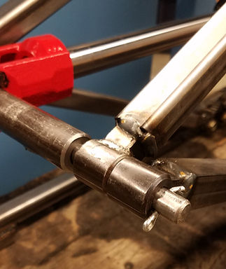
The frame hole location was a crucial aspect of the part, if concentricity wasn't present the link arms wouldn't mesh and the Auto-jack would fail. To ensure that the holes were drilled in the exact location in both the upper and lower frames C-clamps were used on all four corners of frame during the drilling process. With the frames clamped together the frames were then mounted in the vise and the holes were drilled. The drilling process consisted of drilling through both frames in one pass.
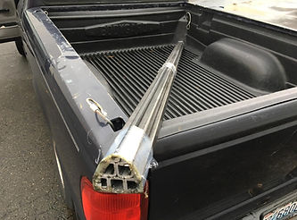
FINAL LOWER/UPPER FRAMES


POWER UNIT PLATE HOLE LAYOUT/DRILLING PROCESS
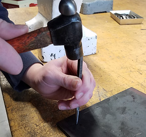
The power unit mounting holes are a critical part in the plate design. If the power unit holes don't line up from layout then the weight distribution throughout the power unit plate will be off-centered and the plate will want to tip over after the wheels are installed. A caliper was used to measure the center distance from the two holes, this was then laid out in sharpie on the power unit plate itself. The holes were then center punched so that the drill press bit had an easier time finding material to cut. No manufacturing issues occurred during the manufacturing of this part.
FINAL POWER UNIT PLATE

.jpg)
VIDEO OF TACK WELDING THE LINK ARMS IN PLACE
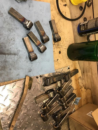
VIDEO OF CUTTING THE FINAL LINK ARMS GEARS
ADDITIONAL MANUFACTURING PHOTOS


.jpg)
